THUNDERMILL01: Lightweight Embedded Electric Field Mill Sensor
The THUNDERMILL01 is an advanced, high-precision electric field mill sensor developed for measuring static and semi-static electric fields. It offers consistent performance in stationary and portable setups in a broad range of meteorological conditions. Its robust design and precise measurement capabilities make it ideal for research institutions, meteorological monitoring, and industrial safety applications.
What Does THUNDERMILL01 Measure?
The THUNDERMILL01 sensor measures the strength and approximate direction of atmospheric electric fields. Atmospheric electric fields result from the distribution of electric charges within clouds, between clouds and the Earth’s surface, and within hydrometeors. By monitoring these fields, THUNDERMILL01 provides data for the enhancement of understanding storm dynamics, lightning activity, and evaluating the risk of electrical discharges. It is particularly valuable for researchers investigating atmospheric phenomena and seeking insight into the electrical interactions occurring during weather events.
Physically, the sensor detects E and dE/dt. It does not, by itself, measure the magnetic field B or the absolute current of a lightning channel — for that, a separate magnetometer or magnetic loop antenna is needed (a magnetic loop antenna picks up dB/dt). To locate the charge change causing a dE/dt feature rather than just detect it, multiple THUNDERMILL01 units must be combined: with four spaced sensors, the TDoA method applied to dE/dt features can locate the charge-transfer event in 3D.
Applications
For detailed practical examples and operational scenarios, refer to Use Cases Documentation.
- Meteorology: UAV-based monitoring and atmospheric analysis.
- Thunderstorm and Weather Research: Detailed observation of storm-induced electric field variations.
- Industrial Safety: Protecting equipment and personnel from electrical discharges.
- Lightning Warning Systems: Real-time monitoring for storm-related safety measures.
- Emergency Management: Decision support data during severe weather events.
- Portable Field Studies: Flexible deployment for temporary measurement campaigns (balloons, drone, cars).
Key Features
- Fast Response Rate: Captures rapid atmospheric phenomena, including lightning.
- Waveform Capture: Provides complete waveforms for in-depth event analysis.
- Real-Time data: Enable instant processing of atmospheric conditions.
- GPS Tagging: Optional time and location tagging of all recorded samples.
- Open-Source: Open-source hardware and firmware
- Portability: Lightweight design applicable to airborne in-situ measurement.
- Compliance: Adheres to IEEE standard 2819-2022 for electromagnetic environment measurement.
Technical Specifications
Some technical parameters, like resolution and measurement range, could be customized for the specific application required by the customer.
| Parameter | Specification |
|---|---|
| Measurement Range | ±100 kV/m |
| Resolution | 50 V/m |
| Accuracy | ±5% |
| Raw Data | Complete waveform capture |
| Processed Output | Electric field intensity |
| E-Field sampling Rate | 25 Hz Typical (Depends on shutter RPM) |
| Time resolution | 521 us (Corresponds to ADC sample rate) |
| Time Tagging | External Multi-constellation GNSS receiver |
| Motor Type | External rotation force (eg. engine, turbine, or popeller rotor) |
| Dimensions | Cylindrical; 80x20 mm |
| Mass | 34 grams (without cabling) |
| Power Consumption | 20 mA@5V + External rotation force (5 W maximum) |
| Data Interface | UART |
| Temperature Range | -40°C to 40°C |
| Humidity Range | 0–90% RH |
| Weatherproof Rating | IP03 |
Measurement Principle and Angular Sensitivity
When positioned in an asymmetric electric field, the EFM produces a periodic signal at the output, corresponding to the charge accumulated in the rotational capacitor formed by the electrodes and the rotating disc. Unlike typical EFMs, whose output is the waveform amplitude often averaged over multiple rotations of the electrode, the THUNDERMILL01 outputs the full waveform of one half-rotation. Each output frame therefore contains a periodic signal whose shape encodes both the field magnitude and the angular orientation of the shutter at the time of a sudden charge change.
The figure below shows how the output waveform depends on the rotational phase of the shutter for different field directions:
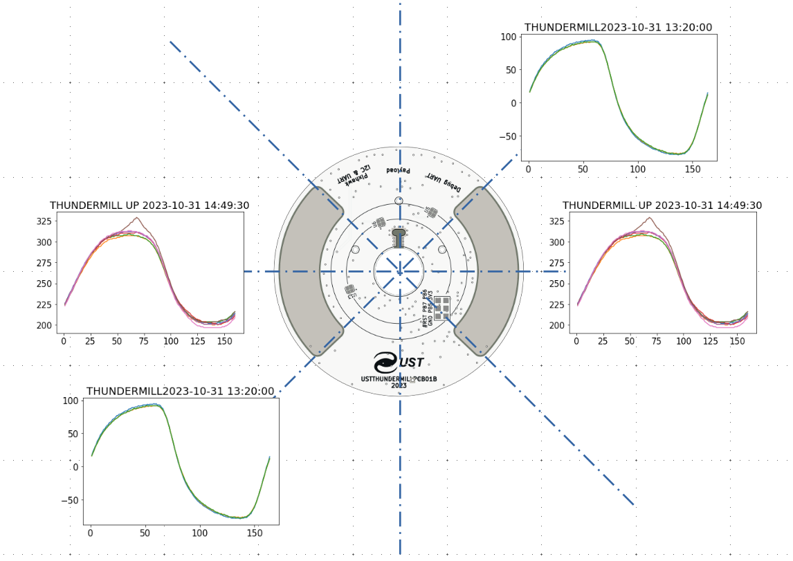
This is the physical basis of the angular sensitivity of THUNDERMILL01 — by digitising the full waveform rather than averaging, the sensor directly outputs the angular phase at which an asymmetric field couples to the electrodes.
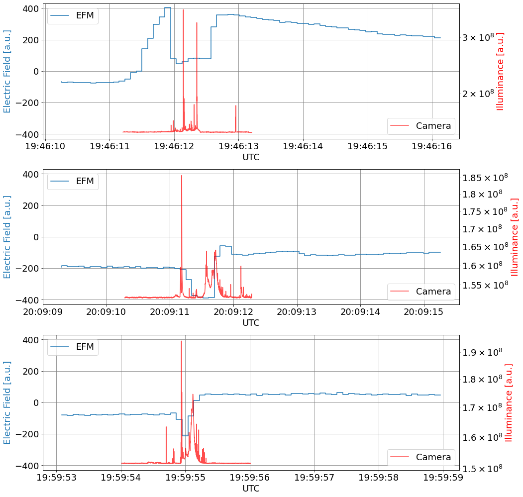
Real-world half-turn output during a lightning event
The two examples below are consecutive half-turns captured 0.086 s apart during the same flash. Note how the waveform deformation appears at a different shutter angle as the lightning charge re-distributes:
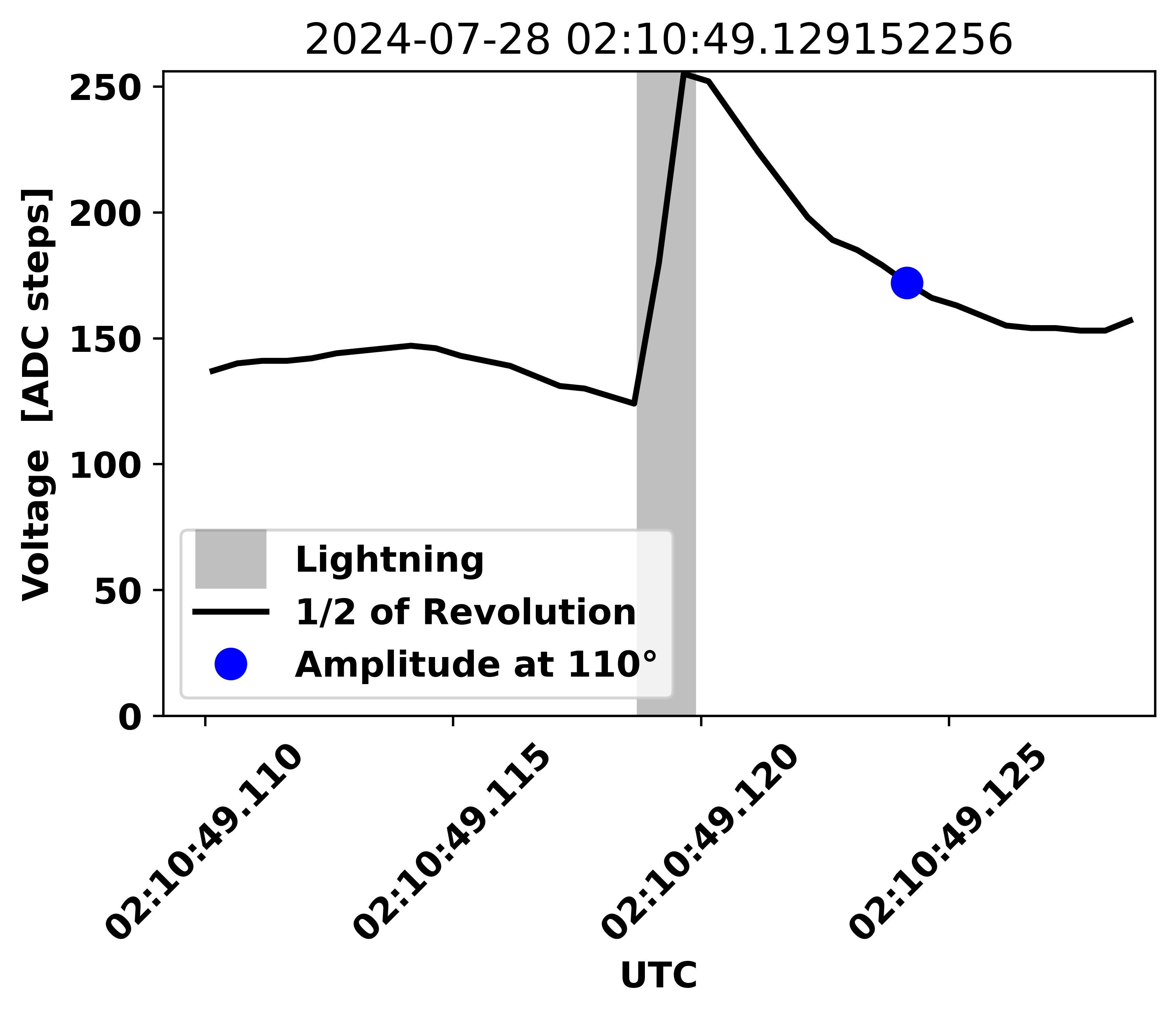
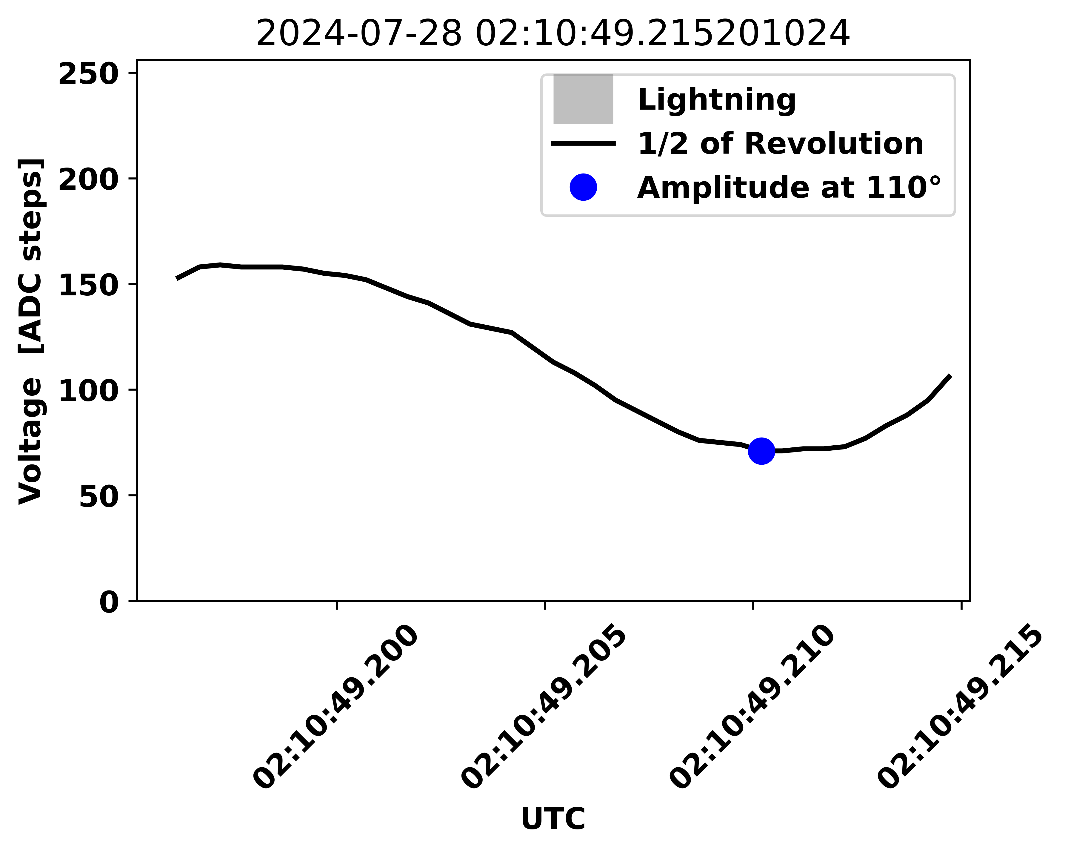
With multiple THUNDERMILL01 sensors deployed in a spaced array, this property enables TDoA-style localization of charge change events at sub-millisecond resolution — see the discussion of E vs. dE/dt detection in What Does THUNDERMILL01 Measure? above.
Comparison with conventional EFMs
THUNDERMILL01 has been benchmarked against the two reference EFMs commonly used in atmospheric research — the Boltek EFM-100 and the Kleinwächter EFM 115. Both comparisons consistently show advantages in measurement range, response flexibility, portability, and most importantly, time resolution.
Side-by-side measurement against Boltek EFM-100
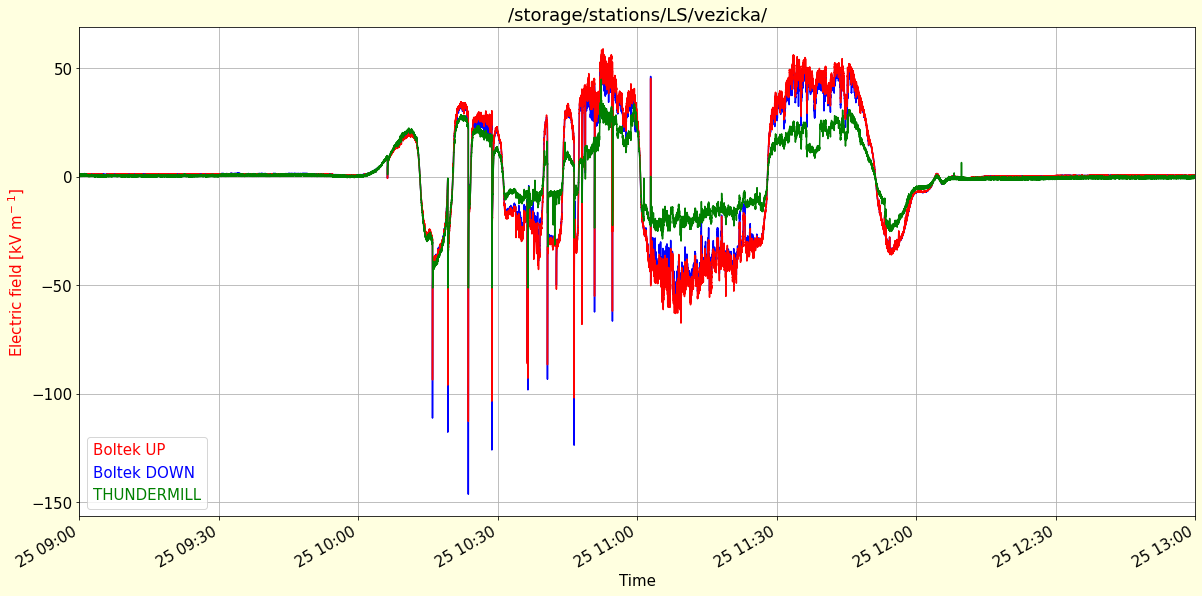
A comparative analysis against conventional sensors (e.g., Boltek EFM-100) has demonstrated significant performance advantages in measurement range, response flexibility, and portability, making THUNDERMILL01 particularly suited for advanced meteorological studies and real-time monitoring scenarios.
Time-resolution advantage over conventional motor-driven EFMs
A conventional motor-driven electric field mill (e.g. Kleinwächter EFM 115) outputs one averaged value per shutter rotation, typically every ~110 ms. This averaging blurs every electric-field change shorter than one rotation and makes it impossible to resolve the per-phase structure of a lightning discharge.
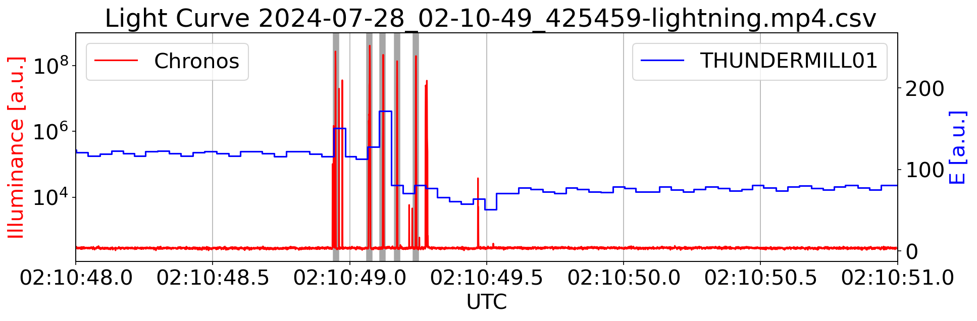
The THUNDERMILL01 instead exposes the raw waveform from each electrode within every half-rotation, with an ADC sample period of 521 µs. The lightning detail captured by the conventional EFM looks like a single step:
The same kind of event captured with THUNDERMILL01 resolves multiple individual electric-field changes within the flash, aligned with the optical luminosity curve from a high-speed all-sky camera:
System Architecture
THUNDERMILL01 is not a standalone instrument. It is intended as a sensing module for integration into a larger host platform, such as ground-based logging unit, stratospheric balloon or UAV.
The device needs to be mechanically integrated into an external system that provides the required supporting functions:
- Power supply for the internal electronics
- UART interface for configuration and data logging
- A source of rotation for the field mill shutter
THUNDERMILL01 itself performs electric field sensing and signal processing, but its operation depends on the surrounding host system. This architecture allows the sensor to be adapted to a wide range of airborne and ground-based applications, while keeping the sensing subsystem compact and modular.
Connector pinouts
TF Payload port
This connector is primarily intended for time synchronization with the TFGPS01 GNSS receiver, which provides location and time pulse signals (PPS) on its “Payload Connector”.
| Signal | Pixhawk Color | ThunderFly Color |
|---|---|---|
| TIMEPULSE |  Black Black |  Blue Blue |
| EXTINT | Black |  Yellow Yellow |
| GPIO | Black |  White White |
| SDA | Black |  Green Green |
| SCL | Black | Yellow |
| TX | Black | White |
| RX | Black | Green |
| GND | Black | Black |
J6 - Debug & programming UART Port
The UART interface is compatible with the Pixhawk connector standard as a peripheral device and enables integration with onboard flight controllers. CTS is disconnected, and the RTS signal is used for the MCU reset for bootloader activation.
| Signal | Pixhawk Color | ThunderFly Color |
|---|---|---|
| +5V |  Red Red | Red |
| RX | Black | White |
| TX | Black | Green |
| Not connected (CTS) | Black | Blue |
| RTS | Black | Yellow |
| GND | Black | Black |
J1 - Pixhawk UART & I2C
| Pin | Signal | Voltage level | Pixhawk Color | ThunderFly Color |
|---|---|---|---|---|
| 1 | VCC | +5V | Red | Red |
| 2 | RX (IN) | +3.3V | Black | White |
| 3 | TX (OUT) | +3.3V | Black | Green |
| 4 | I2C SCL | +3.3V | Black | Yellow |
| 5 | I2C SDA | +3.3V | Black | Green |
| 6 | GND | GND | Black | Black |
Deployments
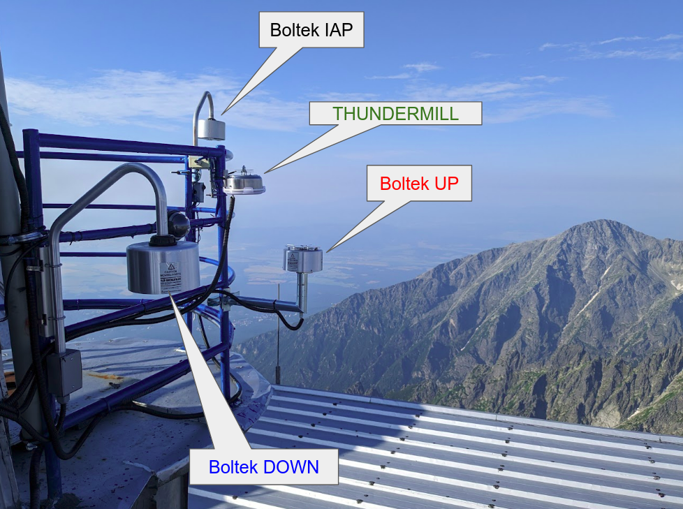
Stationary deployment on a high-altitude observatory
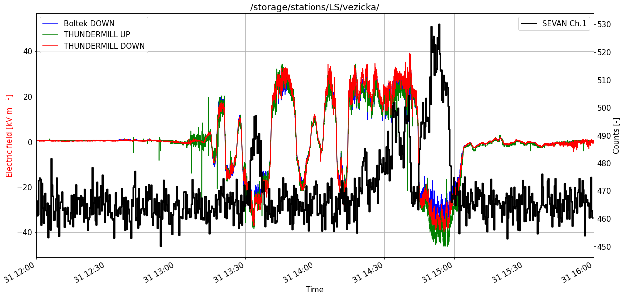
THUNDERMILL01 has been deployed at the Lomnický Štít observatory in both UP and DOWN orientations to measure the charge of falling hydrometeors:

The first measurements on the car roof used a tin-plated can as a temporary weatherproof housing, which rusted through in roughly two months. All subsequent units intended for stationary outdoor placement are built into stainless-steel casings.
A comparison of the two orientations against the co-located Boltek EFM and the SEVAN ionizing radiation detector on the same site is shown below — including the particle flux of secondary cosmic radiation correlated with the electric field excursions:
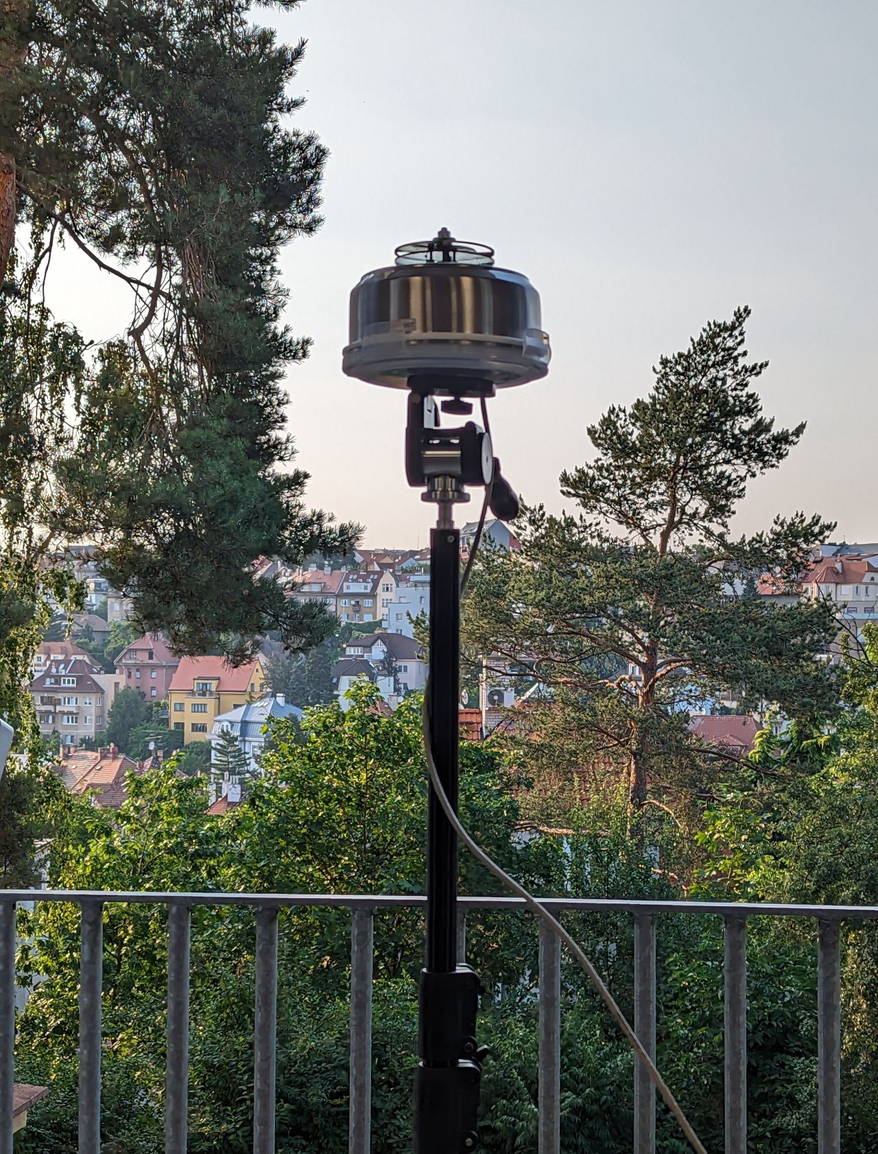
Vehicle-roof deployment
For mobile thunderstorm measurements, THUNDERMILL01 is mounted directly on the roof platform of a measuring car:
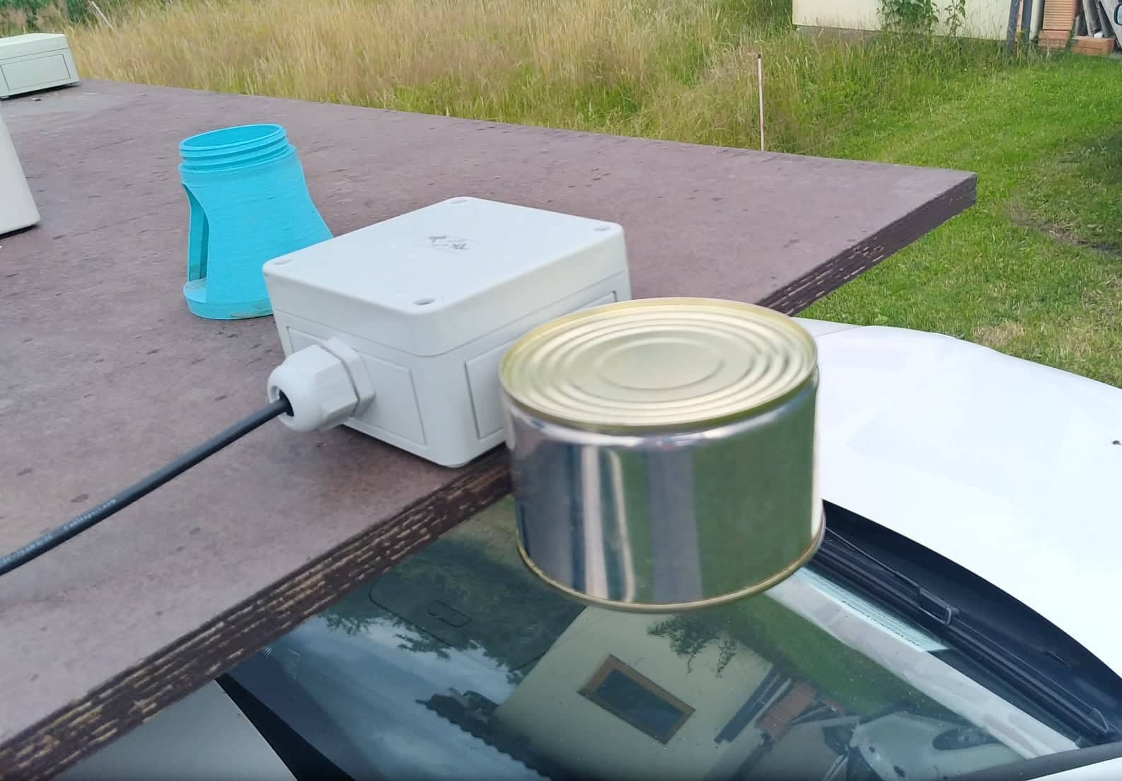
In this configuration the sensor is not grounded to the local soil; it measures the electric-field gradient between the sensing electrodes and the car body. The car body acts as a ground reference at a fixed offset, capturing the vertical electric-field component over the area immediately above the vehicle.
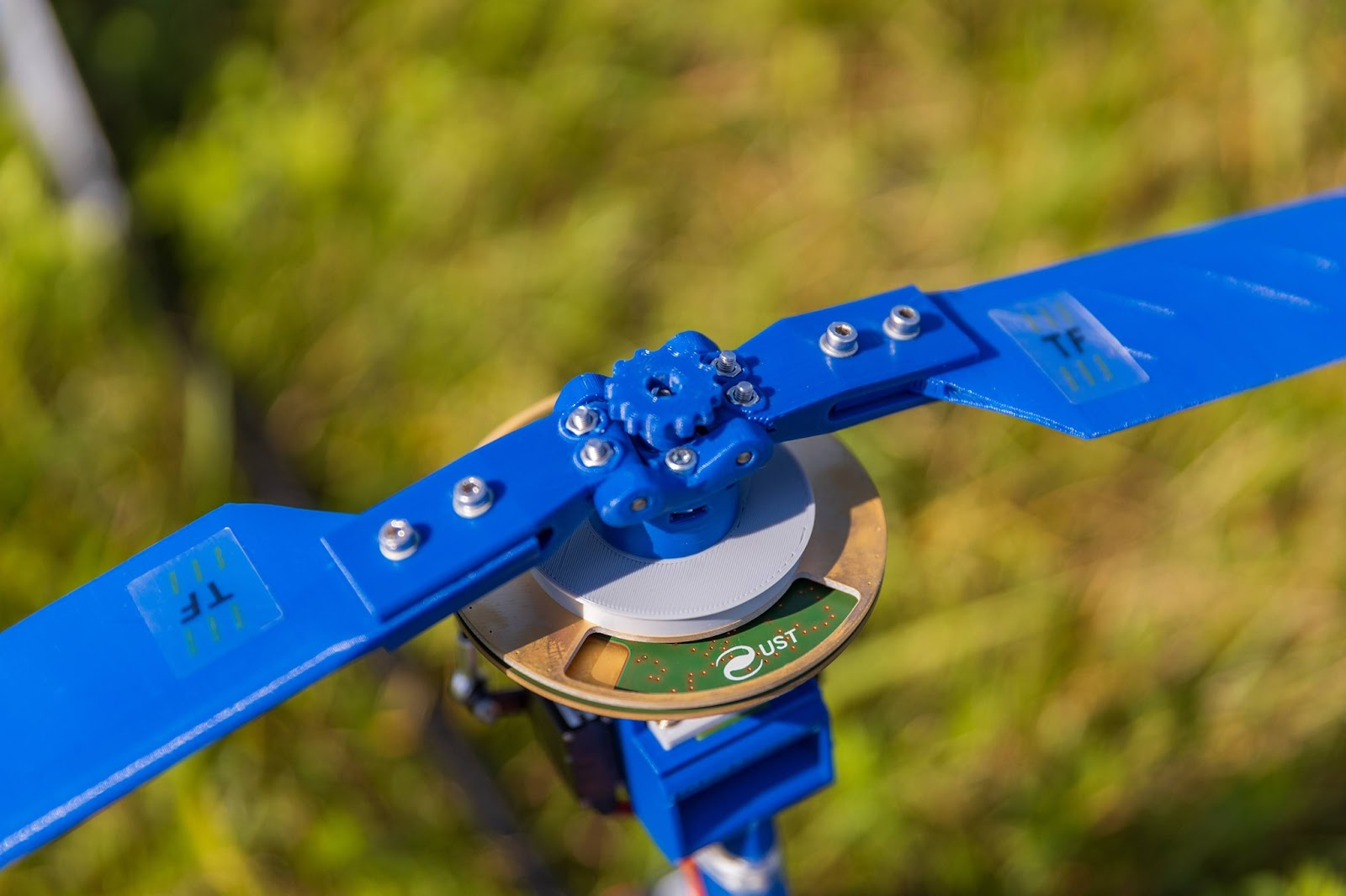
UAV deployment — autogyro rotor head
For in-situ atmospheric measurements, THUNDERMILL01 is integrated into the rotor head of the TF-G2 autogyro UAV. The rotor disk itself serves as the rotating grounded shutter — the autogyro’s rotor is unpowered (autorotation) and freely spinning, which avoids any electromagnetic interference between an active motor and the EFM electrodes. The only electrical requirement is a conductive path from the rotor disk to the measuring electronics through the rotor bearing.
An example of flight data from this configuration, with electric field aligned to humidity, temperature and flight parameters, is shown below:
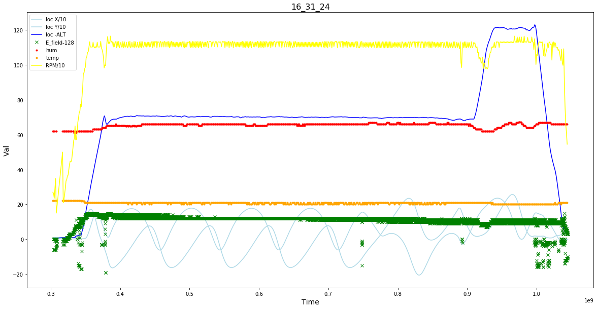
For details of the TF-G2 platform see the ThunderFly TF-G2 documentation.
Experimental Results and Publications
Measurements conducted with THUNDERMILL01 during thunderstorm events have provided insights, notably:
- Enhanced detection and differentiation of atmospheric electric field variations.
- Advanced capability to deduce directional information of electric field sources.
For a discussion of angular‑sensitive electric field mill measurements in thunderstorms, see the paper Measurements with Angular Sensitive Electric Field Mill in Thunderstorms.